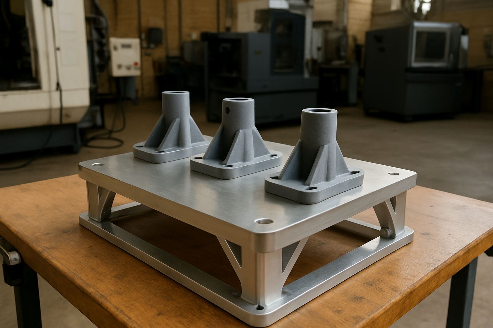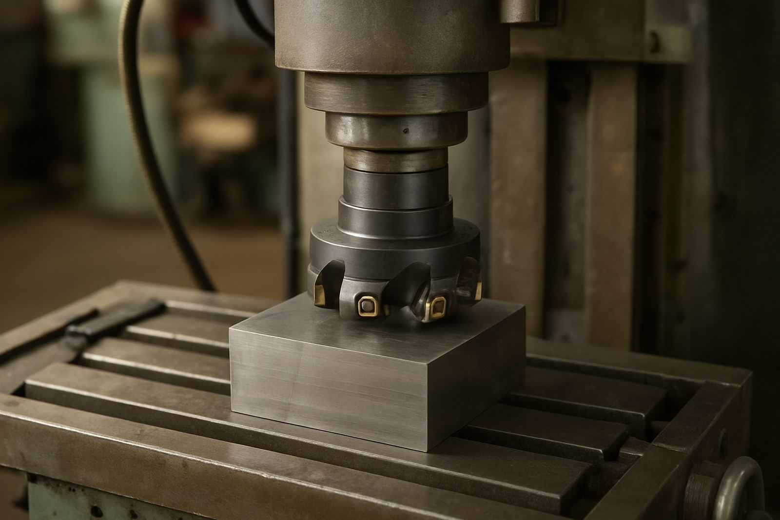

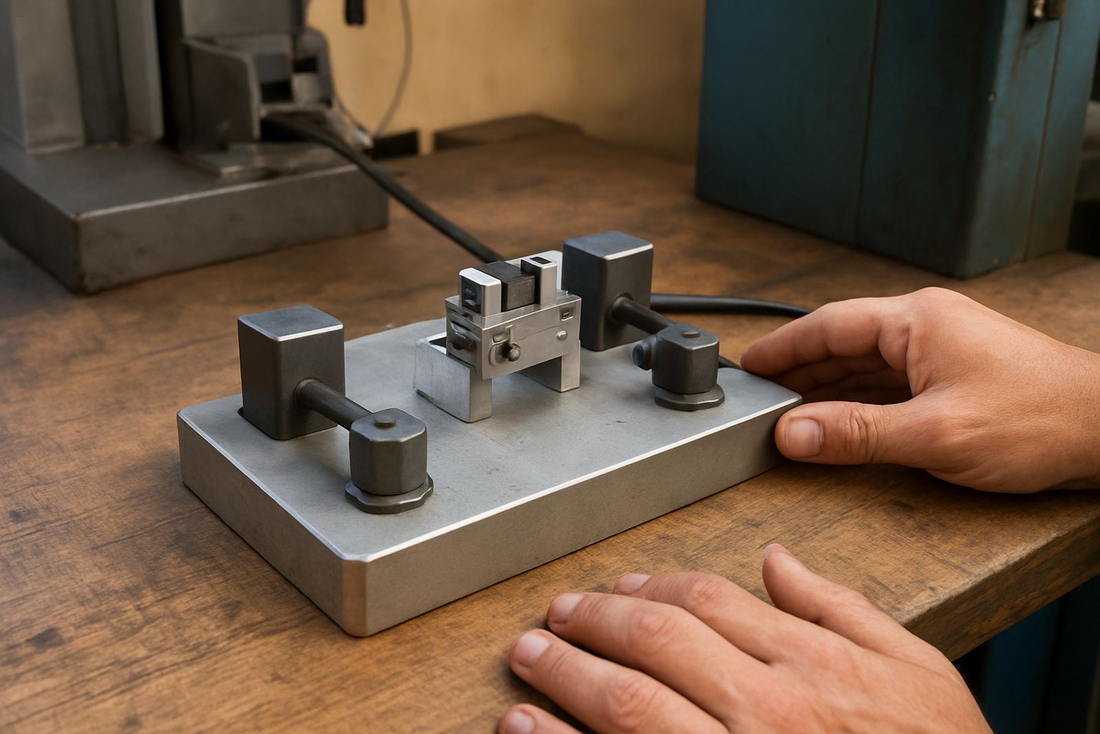
Start with the job, not the print
A good printed jig begins with a clear process map. What part is being held, where does the operator touch it, how many cycles a shift, and what finish is expected at the end of the operation? If the jig only needs to locate a component for drilling, the design can be simple. If it must survive repeated clamping, contact with coolant, or daily transfer between stations, the part needs stronger geometry and better material choice.
In light production, printed jigs work best when they support repeatability rather than carry high cutting loads. They are ideal for assembly guides, inspection nests, drill locators and handling fixtures. They are not a shortcut for poor process planning. A jig that saves 20 seconds per cycle in a batch of 500 parts can justify the full design effort, but only if it keeps the part in the right place every time.
- Define the exact operation first: locate, clamp, drill, inspect, assemble or transfer.
- Measure the part in real conditions, including burrs, paint, cast surfaces or moulded variation.
- Allow for operator access so hands, gauges and tools can reach the part without forcing it.
Choose a material that suits heat, wear and handling
Material choice matters more than many shops expect. A jig used near a warm machine bed, under fluorescent lights all day, or in a coastal workshop with humidity will behave differently from one kept in a clean air-conditioned room. In Gqeberha, salt in the air can also affect metal inserts and fasteners, so printed parts should not be asked to do everything on their own.
For general light production, a tougher engineering-grade plastic is usually preferred over brittle stock. If the jig will see repeated clamp pressure or sliding contact, add metal wear surfaces, threaded inserts, or replaceable pads. When the part is exposed to washdown, coolant, or sunlight near a loading bay, check whether the chosen material will warp, soften or fade. A simple printed shell with proper reinforcement often lasts longer than a heavy solid print that traps heat and cracks at the corners.
- Use thicker sections around clamp points and screw locations.
- Add fillets to inside corners to reduce stress concentration.
- Keep long unsupported spans to a minimum, especially on tall locating features.
Build in tolerance where the shop floor needs it
Printed jigs should locate the workpiece accurately, but they also need a little forgiveness. Parts from pressing, cutting or moulding often vary by a fraction of a millimetre, and a tight print with no clearance can become difficult to use after a few days. Good jig design balances location with practical loading. A chamfer, lead-in or tapered pocket can make a big difference to cycle time and operator confidence.
It is also worth thinking about runout, alignment and repeatability in the same way a machine shop thinks about tooling. If a jig has to position a bore for hand drilling, then the locating face, bushing position and clamping pressure all need to work together. On a small production line in Markman, for example, a printed assembly jig for bracket drilling may need slightly oversize entry holes, a hardened insert at the drill point, and a stop that is easy to inspect at the start of each shift. That saves rework when the load-shedding backup routine changes the pace of the job and operators are moving faster than usual.
- Allow clearance for part variation, paint build-up and surface texture.
- Use datum points that are easy to inspect visually.
- Design for quick part loading so the operator does not force the component into position.
Reinforce the places that fail first
Most printed jigs fail at the same places: clamp points, thin walls, sharp corners and threaded holes. Those areas must be treated as wear zones. If a jig is going to be handled all day, the corners should be rounded and the edges thick enough to resist chipping when it is placed on a steel bench. Where possible, design the part so the load spreads across a larger surface instead of concentrating at one point.
Printed threads are often the first thing to strip in a production environment. For that reason, inserts are usually a better choice than relying on plastic alone. The same applies to guide bushes and stop pins. If the feature must stay accurate over many cycles, make it replaceable. That approach costs a little more upfront but keeps the jig in service longer and makes maintenance easier for the machine shop.
For Durban road freight delays or inter-branch transfers between Struandale, Coega and Despatch, a jig that can be broken down into a base and replaceable wear parts is also easier to pack and service. It is practical and it keeps downtime lower when one station is waiting on another.
Design for cleaning, storage and daily use
A durable jig is one that a team can actually look after. If coolant, dust or chips collect in cavities, the fixture will become awkward to use and harder to inspect. Printed jigs should have drain paths, open corners where possible, and surfaces that can be wiped down without trapping grime. In a busy workshop, the easiest jig to clean is the one that gets used properly and lasts longer.
Storage matters too. A jig left near a heat source, on a window sill, or in a tray under heavy steel offcuts will deform or crack long before the material reaches its design life. Label the orientation, the part number, and the station if there is more than one version. That helps operators return the fixture to the right place and reduces the chance of the wrong jig ending up on the wrong job.
- Keep surfaces accessible for wiping and inspection.
- Mark the correct orientation clearly on the fixture.
- Avoid hidden cavities where chips, dust and coolant can build up.
A simple local example from a Gqeberha line
A small metal parts shop in the Struandale area may need a printed jig for marking and drilling a light bracket used in automotive sub-assembly. The part is not heavy, but the batch size is steady and the operator has to move fast. A well designed printed jig can locate the bracket against two datums, hold it with a quick clamp and provide a hardened drill guide where the hole must stay true.
In that situation, the jig does not need to look complicated. It needs to be repeatable, easy to clean and cheap enough to replace only the wear component if damage occurs. If the shop is working around power interruptions, a fixture that sets up quickly and does not need powered clamping can also keep production moving. The right printed jig will not replace proper machining practice, but it can reduce handling time, cut errors and keep small batches profitable.
That is the real value in printed jig design: not novelty, but control. When the fixture is designed for the part, the people and the production rate, it becomes a proper shop-floor tool instead of a temporary fix.